How to repair a cut fibre optic cable — 3 methods explained

Table of contents
A cut fibre optic cable means a dead network link — and unlike a copper cable, you cannot repair a fibre with tape. The good news: a cut fibre is fully repairable, with near-new results if the right method is chosen. This guide presents the 3 repair methods, the required tools and the step-by-step procedure to restore your link without replacing the entire cable.
The quality of a fibre repair is measured in dB of loss at the splice. A well-executed fusion splice adds less than 0.1 dB — virtually imperceptible. A quality mechanical splice stays below 0.5 dB.
Step 1 — Pinpoint the break
Before any repair, you need to know exactly where the cable is cut. A clean visible break is the simple case — but a fibre can also be broken inside its jacket due to crushing, excessive bending or mechanical shock, with no visible external damage.
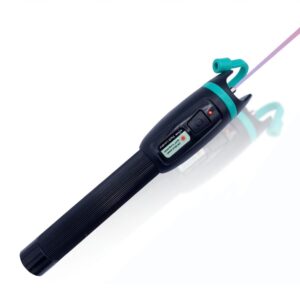
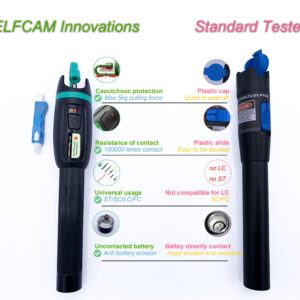
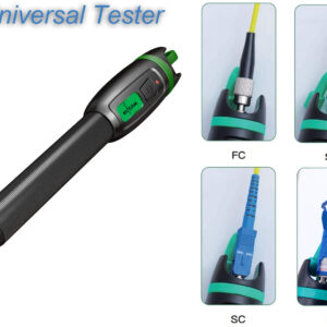
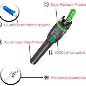
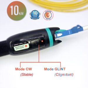
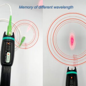
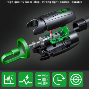
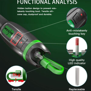
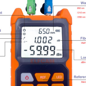
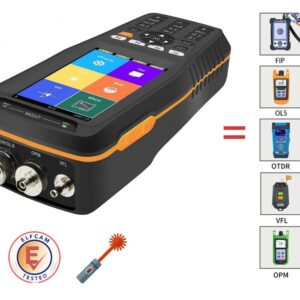
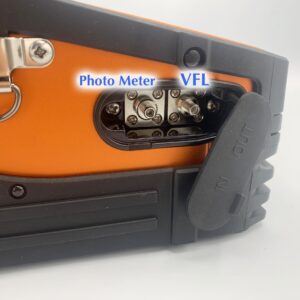
Tool 1 — VFL (Visual Fault Locator): The VFL pen injects visible red light (650 nm, 1–10 mW) into the fibre. The light "leaks" at the break point, revealing its exact position even through a transparent jacket. Effective for breaks less than 5 km from the end.
Tool 2 — OTDR (reflectometer): For breaks over long distances or when the cable is concealed, the OTDR sends light pulses and measures the reflections. It locates the break with an accuracy of ±1 m and indicates the exact distance from the end. Essential for outdoor or underground links.
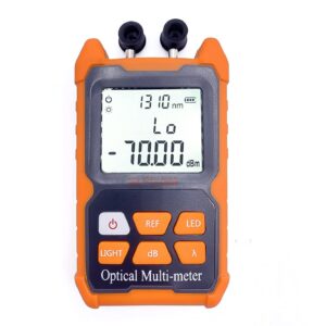
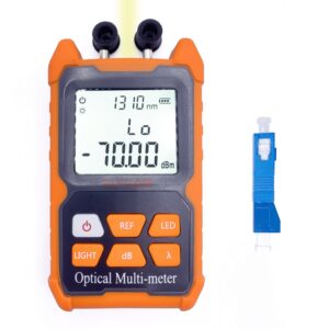
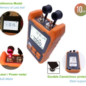
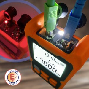
Tool 3 — Continuity tester: Without an OTDR, simply inject a light source at one end. If no light is visible at the other end, the fibre is indeed cut (or the connector is dirty — clean it first before concluding).


The 3 repair methods — comparison
| Method | Splice loss | Durability | Required equipment | Use case |
|---|---|---|---|---|
| Fusion splicing | < 0.1 dB | Permanent (20+ years) | Arc fusion splicer, cleaver | Any permanent repair |
| Mechanical splice | 0.2–0.5 dB | Good (5–10 years) | Mechanical splice kit, cleaver | Quick repair, no splicer |
| Patch cord replacement | 0.3–0.5 dB (×2 connectors) | Permanent | None (pre-terminated cable) | Short accessible cable, FTTH |
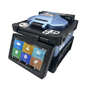
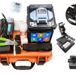
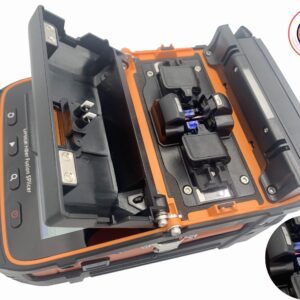
Method 1 — Fusion splicing (recommended)
Fusion splicing is the professional reference method. It consists of aligning and fusing the two fibre ends with an electric arc, creating a near-perfect joint. Losses are minimal (< 0.1 dB) and the repair is permanent.
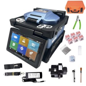
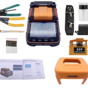
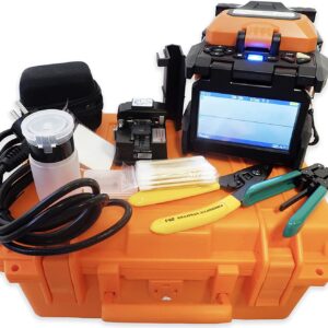
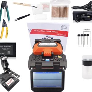
Required equipment:
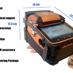
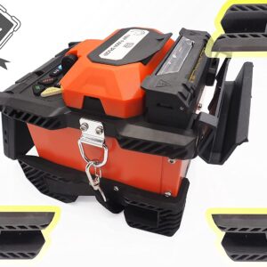
- Arc fusion splicer — automatically aligns the fibres and performs the fusion
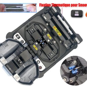
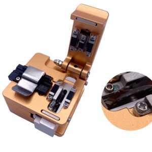
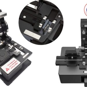
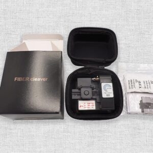
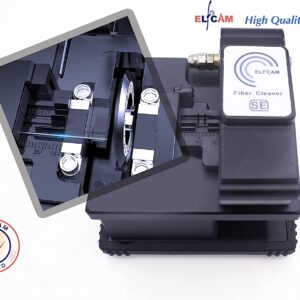
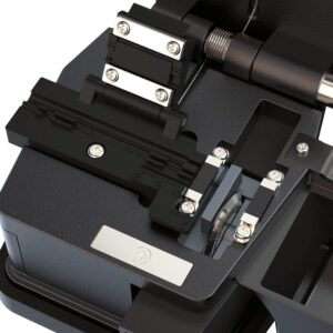
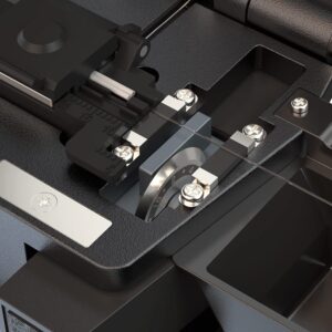
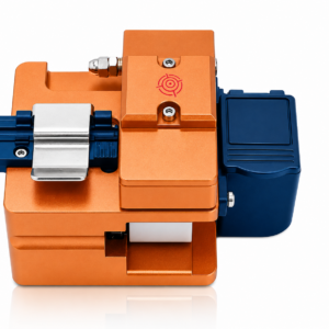
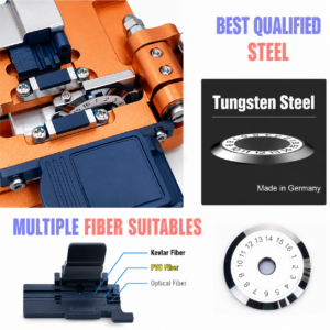
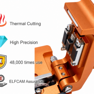
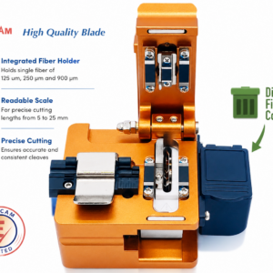
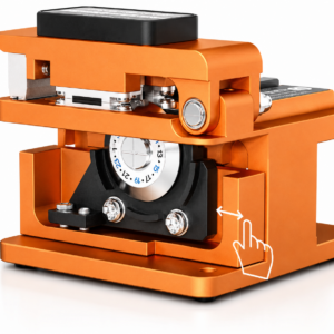
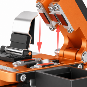
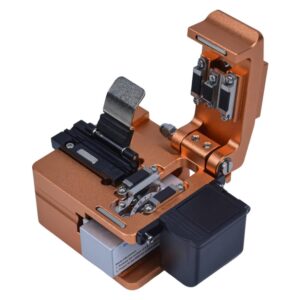
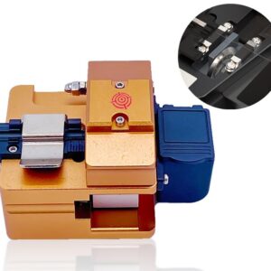
- Precision cleaver — cuts the fibre with a perfectly flat face (angle < 0.5°)
- Fibre stripper and buffer stripper — to prepare the ends
- Heat shrink splice protection sleeves — to protect the spliced area
- Lint-free IPA 99% wipes — to clean the fibres before splicing
Step-by-step procedure:
- 1. Cut cleanly — recut both ends of the cable on either side of the damaged area, leaving enough length to work with (20–30 cm on each side)
- 2. Thread the sleeve — slide the heat shrink sleeve onto one of the fibres before any splicing (classic mistake to forget it)
- 3. Strip the cable — remove the outer jacket over 3–5 cm with the cable stripper
- 4. Strip the fibre — remove the acrylic coating over 2–3 cm with the Fiber Stripper
- 5. Clean — wipe the bare fibre with an IPA 99% wipe in a single direction
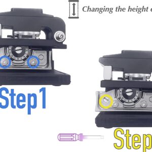
- 6. Cleave — cut the fibre with the cleaver. Visually check the quality of the cut (smooth, perpendicular face)
- 7. Repeat steps 3–6 for the second fibre
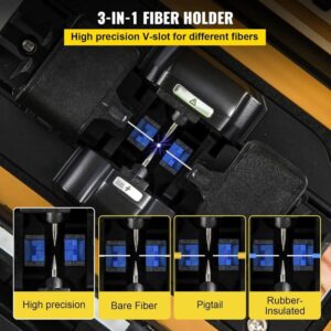
- 8. Place into the splicer — set both fibres into the splicer clamps, face to face
- 9. Start the fusion — the splicer automatically aligns the fibres (core-to-core alignment on premium models) and performs the splice. It displays the estimated loss (< 0.1 dB = good result)
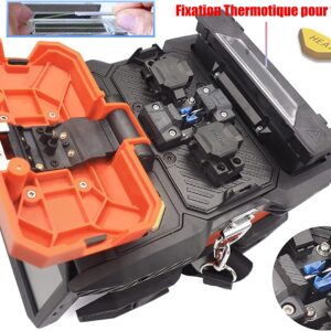
- 10. Protect the splice — slide the sleeve over the spliced area and shrink it in the splicer's oven
- 11. Store in the splice tray — place the spliced fibre in a splice tray to protect it mechanically


Pro tip
On modern splicers with core-to-core alignment (6 motors), the average loss is 0.02 dB — twice as good as cladding-alignment models. For critical links or long distances, prefer this type of splicer.
Method 2 — Mechanical splice
The mechanical splice lets you repair a fibre without an arc splicer. A mechanical connector holds the two fibre ends in contact thanks to an index-matching gel that reduces reflections at the joint.
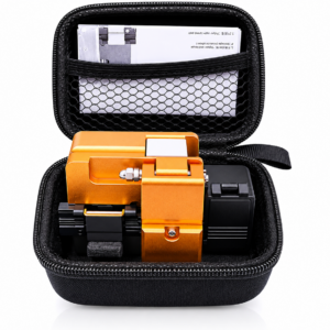
Advantages: fast (2–3 minutes per splice), no expensive equipment, easily portable in the field.
Drawbacks: higher losses (0.2–0.5 dB), sensitive to vibrations over time, shorter lifespan than a fusion splice.
Procedure: Strip, decap, clean and cleave both ends (identical to splicing). Insert each fibre into the mechanical connector from either side until they touch. Clip the mechanism to maintain pressure. Check continuity with a VFL.

Method 3 — Patch cord replacement
If the cut cable is a short and accessible patch cord (patch cable in a rack, FTTH connection between the wall outlet and the box), the simplest solution is often to replace the entire cable with a new pre-terminated patch cord.
This method requires no specialised tools — just unplug the old cable and plug in the new one. It is suitable for the following situations:
- Patch cable in a server room or network rack (lengths from 0.5 to 5 m)
- FTTH connection between the wall outlet and the operator's ONT/box (SC/APC or LC/APC)
- Short link between two active devices (switch, ONU, transceiver)
- Outdoor patch cord accessible along its entire length (full replacement)

Elfcam replacement patch cords
- Indoor fibre optic patch cords — SC/APC, LC/APC, LC/UPC, OM3/OS2, available from 0.5 m to 100 m
- Armoured outdoor fibre cables — for outdoor links between buildings, UV and moisture resistant
Testing the repair
Whatever method is used, systematically test the link after repair before putting it back into service.
Quick test — VFL: Inject red light at one end. If the light is visible at the other end with no visible leak at the splice, continuity is restored.
Qualification test — Attenuation measurement: Use a power meter to measure the total loss of the link. Compare with the cable's theoretical loss (0.3–0.4 dB/km for OS2) plus the loss of your connectors and splices. A successful repair must add:
- Fusion splicing: < 0.1 dB at the splice
- Mechanical splice: 0.2–0.5 dB at the splice
- If the loss exceeds these values: redo the cleave and restart the splice
Full test — OTDR: For a professional repair to be delivered to a customer, run a bidirectional OTDR trace (from both ends). The trace shows the splice with its exact loss and confirms there are no other anomalies on the link.
When to call a professional?
Some situations go beyond a DIY repair:
- Multi-fibre cable (12, 24, 48 fibres or more) — each fibre must be spliced individually, which is a long and precise operation
- Underground or buried cable — repair requires excavation and a watertight splice closure (IP68)
- Critical production link — a poor repair can cause intermittent losses that are harder to diagnose than the original break
- No splicer on site — renting or calling in an equipped technician is often more cost-effective than buying a splicer for a one-off repair
- Cable under operator contract — the repair must be carried out by a certified installer to maintain the warranty