How to install a fiber optic cable — Complete step-by-step guide
Contents
Installing a fiber optic cable often intimidates the uninitiated. Microscopic connectors, critical bend radii, reflectometry tests — on paper, it looks like surgery. In practice, with the right method and the right tools, an experienced technician can lay an indoor fiber link in less than half a day, and an outdoor link in a day. This guide gives you every step in order, without any guesswork.
A poorly installed fiber link does not fail suddenly — it silently degrades performance. The method matters as much as the equipment.
The essential tools before you begin
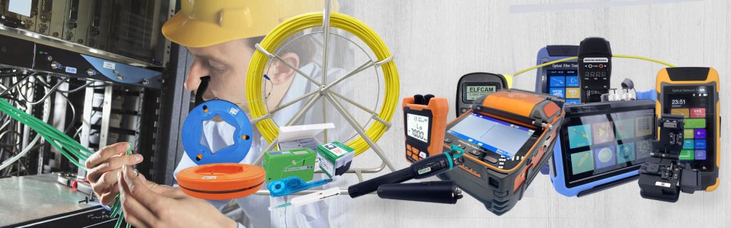
Before pulling the first meter of cable, make sure you have all of these tools. A fiber installation aborted halfway through for lack of a tool costs more than good initial preparation.
Cable preparation tools:
- Fiber cable stripper — to remove the outer jacket without damaging the fibers
- Precision cleaver — a clean cut perpendicular to the fiber, essential for a clean splice or connector
- Arc fusion splicer (fusion splicer) — for fusion splices, or a mechanical connector kit for simpler installations
- Fiber Stripper — removes the 250 µm acrylic coating around the bare fiber
Pulling and laying tools:
- Fish tape or pulling cable — to run the cable through the conduits
- PVC or ICTA conduit — mandatory mechanical protection for surface-mounted or in-slab installations
- Fixing clamps and clips — to hold the cable without compressing it
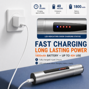
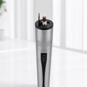
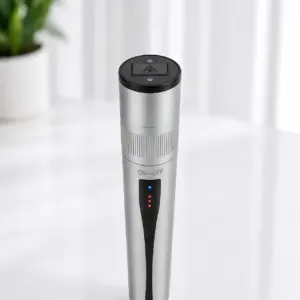
- Optical continuity tester (light source + photodetector) — quick check before splicing
Testing and validation tools:
- OTDR (reflectometer) — measures reflection losses and locates faults on the link
- Optical power meter (power meter) — measures the total attenuation of the link
- Connector inspection microscope — checks the cleanliness of the connector face before connecting
Tip
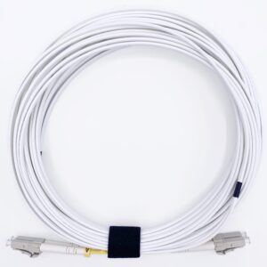
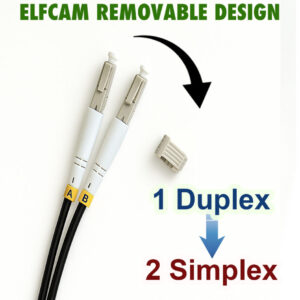
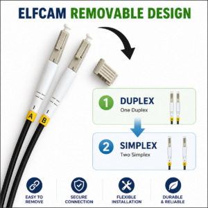
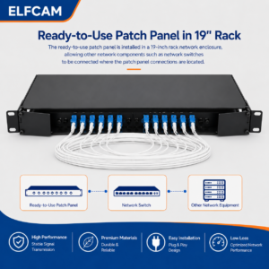
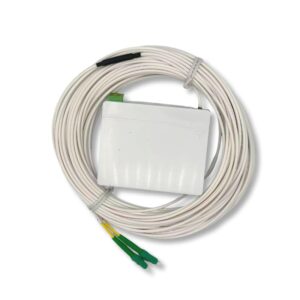
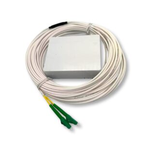
For a simple residential installation (FTTH connection, short point-to-point link), a preconnectorized patch cord eliminates the splicing and connectorization steps. You only need a fish tape and a continuity tester.
Plan the fiber optic cable route
Planning the route is the most important step — and the one most often rushed. A poor route forces overly tight bends, mechanical stress points, or excessive lengths that increase attenuation.
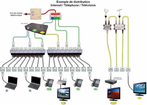
Identify the start and end points (PBO, PTO, technical room, patch panel), then map the path while following these rules:
- Minimum bend radius — never less than 10× the cable diameter (typically 30–50 mm for a standard indoor cable). Below that, the fibers deform and attenuation skyrockets.
- Total length — include a margin of 10 to 15 % for unforeseen detours and slack loops at the ends
- Slab or wall crossings — provide ICTA ducting before pouring the concrete or closing up the partitions
- Separation from electrical cables — fiber is not sensitive to electromagnetic fields, but keep 5 cm of distance for ease of maintenance
- Accessibility of splice boxes — they must remain accessible for future interventions
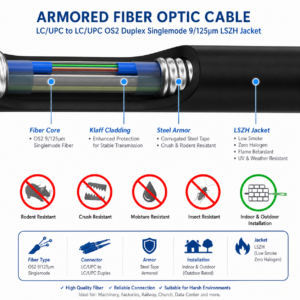
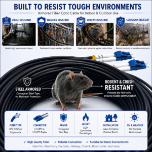
Choose the right cable for the environment
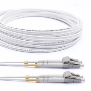
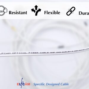
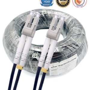
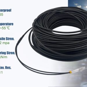
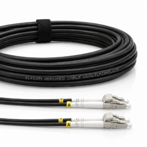
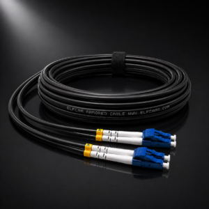
The choice of cable determines the entire installation. An indoor cable laid outdoors degrades within a few months under the effect of UV and humidity. An armored outdoor cable installed indoors is harder to handle and more expensive for no reason.
| Criterion | Indoor cable | Armored outdoor cable |
|---|---|---|
| Environment | Dry indoors, sheath, conduit | Outdoor, buried, facade |
| Outer jacket | Flexible PVC | Armored steel + black PE |
| UV resistance | No | Yes (black PE jacket) |
| Humidity resistance | Low | Built-in hydrophobic gel |
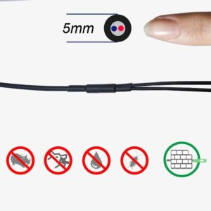
| Rodent resistance | No | Yes (steel armor) |
| Bend radius | 30 mm min | 50 mm min |
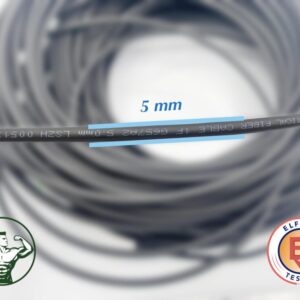
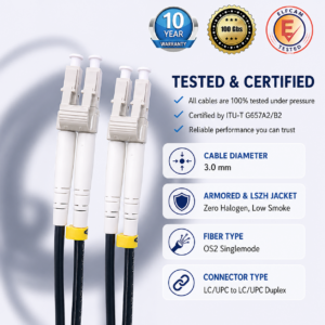
| Typical diameter | 2–3 mm | 8–12 mm |
| Buried installation | No | Yes (with ducting) |
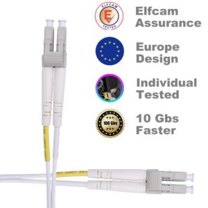
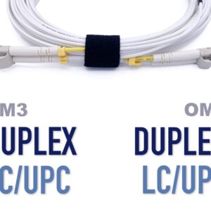
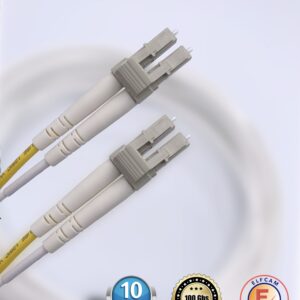
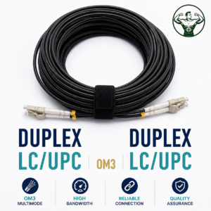
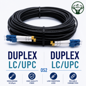
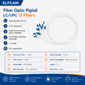
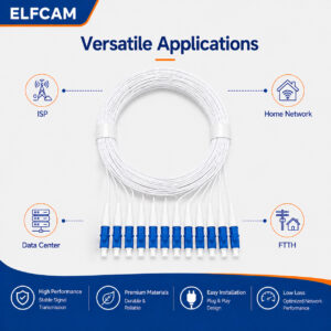
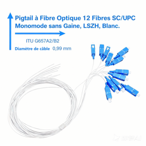
For single-mode fiber (OS2), the signal can travel several kilometers — ideal for long-distance links between buildings. For multimode fiber (OM3/OM4), the range is limited to 300–400 m at 10G but the tolerance to connectors is greater, which simplifies small business installations.


Prepare and pull the fiber optic cable
Pulling the cable is the most physical step of the installation. The golden rule: never force it. The fiber withstands limited tension (typically 100–600 N depending on the cable), and a kink (sharp bend) creates a permanent signal loss invisible to the naked eye.
Conduit pulling procedure:
- First run the fish tape through the conduit along its entire length before attaching the cable
- Attach the cable to the fish tape with a pulling sleeve (avoids concentrating the tension on the fibers)
- Pull steadily and slowly — feed the cable from the starting end at the same time as you pull from the other end if possible
- If the cable resists, check the bends and friction points — use talc or appropriate pulling grease
- Leave a slack of 1 to 2 m at each end for connections and future rewiring
Surface mounting (without conduit):
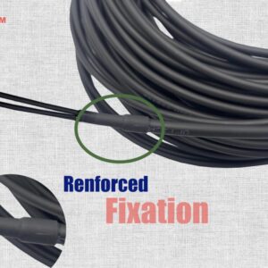
- Fix the cable with loose plastic clips — never compress the jacket
- Create bends with a respected radius — use bend guides at changes of direction
- For wall mounting, space the fixings 40–60 cm apart to prevent the cable from sagging
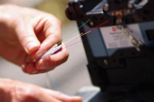
Splice and connect the fibers
This is the precision step. There are two main methods for terminating a fiber: fusion splicing (thermal splice) and mechanical connectorization (compression or polished connector). Fusion offers far lower losses (< 0.1 dB) but requires an arc fusion splicer. Mechanical connectors are more accessible but show losses of 0.2 to 0.5 dB.
Connectorization steps (connector method):
- Strip the cable — remove the outer jacket over 3–5 cm with the appropriate stripper
- Strip the fiber — remove the acrylic coating over 2–3 cm with the Fiber Stripper
- Clean — wipe the bare fiber with a lint-free 99 % IPA wipe
- Cleave — cut the fiber with the precision cleaver. The face must be flat and perpendicular (angle < 0.5°)
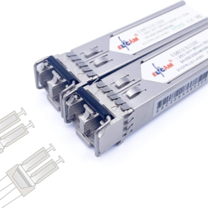
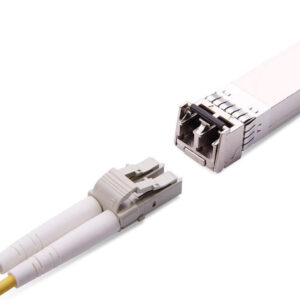
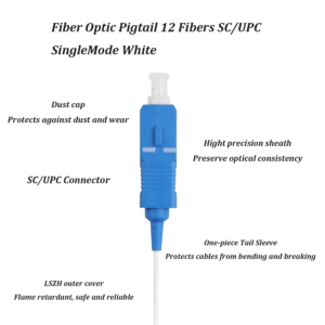
- Insert into the connector — insert the fiber into the LC, SC or other connector all the way to the bottom
- Crimp or glue — depending on the connector type (epoxy, press-fit, index-matching gel)
- Polish the face — for epoxy connectors, polish progressively (12 µm → 1 µm paper)
- Inspect — check the face under a 200× microscope before any connection
Test and validate the fiber optic installation
No fiber installation should be put into service without validation. Losses invisible to the naked eye can halve the throughput or make the link unstable under load. Two levels of testing are recommended:
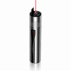
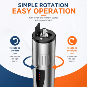
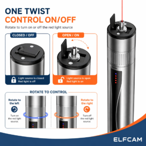
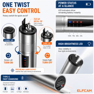
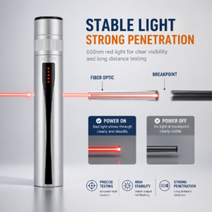
Test 1 — Optical continuity (quick test): Inject visible light (red 650 nm source) from one end. The light must be visible at the other end. This test confirms that the fiber is continuous and not broken, but does not measure losses.
Test 2 — Attenuation measurement (qualification test): Use a calibrated optical transmitter and a photodetector (power meter) to measure the total loss of the link in dB. Compare with the calculated optical budget:
- OM3 fiber, 100 m link, 2 connectors: expected total loss ≈ 0.5 + 2 × 0.3 = 1.1 dB max
- OS2 fiber, 500 m link, 4 connectors: expected total loss ≈ 0.18 + 4 × 0.3 = 1.38 dB max
- If the measurement exceeds the budget: look for a dirty connector, a kink, or a poorly fused splice
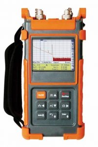
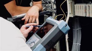
Test 3 — OTDR (diagnostic test): The reflectometer sends light pulses and measures the reflections. It produces a trace that shows every connector, every splice and every anomaly with its precise position in meters. Essential for long links or as part of a customer delivery.
Mistakes not to make
These mistakes are the most common in the field — and the most costly to troubleshoot:
- Bending the cable at a sharp angle — a sharp bend permanently breaks or deforms the fibers
- Connecting without inspecting — a dust particle on a connector face causes 1 to 3 dB of additional loss
- Tightening the fixing clamps — lateral pressure on the cable creates bending losses (macro-bending)
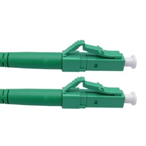
- Confusing APC and UPC — an SC/APC connector (green bevel) must never be connected to an SC/UPC (blue face) without a hybrid adapter
- Mixing OM3 and OM4 in the same link — the fibers are compatible but performance is limited by the weakest link
- Forgetting slack loops — always leave 1 m of slack in the splice boxes for future reworks
- Not protecting the ends — keep the protective caps on all unused connectors